FEA (Finite Element Analysis) used to be considered to be something of a “black art” practiced only by specialists using (expensive) specialist tools. That’s no longer the case, as CAD tool vendors have since given designers easy access to FEA (and for that matter CFD too) by incorporating established CAE solvers into their CAD software. With pre- and post-processing done in the CAD domain using familiar menus it’s easy for designers to use. The CAD vendors have really delivered a useful add-on to their software and have brought FEA to the masses. So, what’s wrong with that?
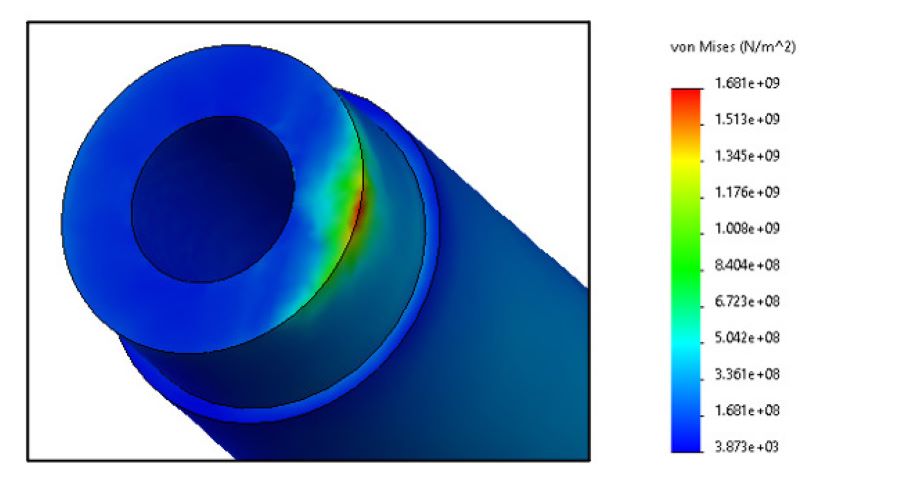
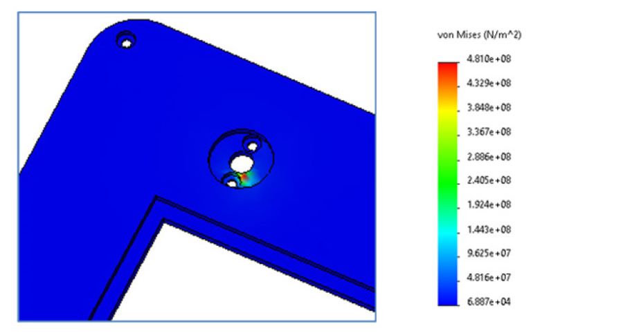
We recently performed a linear-elastic stress analysis of a structure which featured a rod within a hole in a thick plate. The rod was a precision clearance in the hole, so a close fit. There was a sideways load on the end of the rod which resulted in it bearing on the surface of the hole. Even with refined mesh around the hole / rod interface, the stresses in both the rod and the plate were well in excess of the material yield strength resulting in a Reserve Factor (RF) of 0.12 and 0.56 for the rod and the plate respectively. With acceptance criterion of 1.0, this signals a clear failure of both parts.


In the strictly exact world of CAD, if there is clearance between the rod and the hole then the diameters are different, in which case the contact between them is a 1-D line. Worst still, if the loading on the rod results in bending rather than translation, the contact is theoretically a point. Such is the case with our example.
Both the line and the point have zero area. As Stress=Load/Area it can be seen that when loads are applied to areas that are approaching zero the resulting stresses are inversely very large.
Regular linear-elastic FEA tools are not equipped to deal with this phenomenon and as a result are incapable of generating correct results. The resulting high stresses are known as “artefacts” of FEA, which in practice are simply disregarded by users. So, how then do we know that the design is sound?
Back to the pen and paper
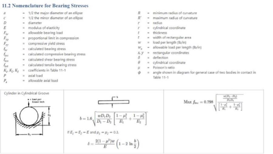
Bearing stresses can be more accurately predicted through the use of formulae derived empirically, an example of which is illustrated below:

Original source: the “Stress Analysis Manual,” Air Force Flight Dynamics Laboratory, October 1986.
Using the formulae above the Reserve Factors for the rod and the plate calculate to be 3.4 and 2.8 respectively (compared to 0.12 and 0.56 through FEA). The difference is hugely significant as it is literally the difference between the design being predicted to fail miserably and to pass by a respectable margin.
The issue with the way that FEA has been democratised is that no vendor provides a mechanism that can warn the user when the results generated are likely to be incorrect. In addition, no guidance is provided as to what next steps need to be taken if an analysis is likely to deliver incorrect results. That is still down to old-fashioned knowledge and experience.


